Inductance
Table of Content |
 We have already discussed the topic of capacitors which are the devices to store energy using electric fields. Like a capacitor, an inductor is also quite commonly used element in electric circuits. It stores magnetic energy. As we know that when current flows through a conductor, a magnetic field is set-up in surrounding of it, and hence it is associated with magnetic flux. If magnetic flux associated with a coil is Φ and current flowing through it is I, then its inductance is given by the expression L=Φ ⁄ l. The quantity 'L' is called self-inductance of the coil. It does not depend on the current, but it depends on the permeability of the core and the dimensions of the coil.
In 1824, Oersted discovered that current passing through a coil created a magnetic field capable of shifting a compass needle. After a span of seven years, Faraday and Henry discovered just the opposite. They noticed that a moving magnetic field would induce current in an electrical conductor. The process of generating electrical current in a conductor by placing the conductor in a changing magnetic field is called electromagnetic induction or just induction. It is called induction because the current is induced in the conductor by the magnetic field.
Inductance occurs on the occurrence of induction in an electric circuit which affects the flow of electricity. It is denoted by the letter L. Self-inductance or simply inductance may hence be defined as the property of a circuit wherein a change in current leads to a change in the voltage in the same circuit. When a current flow is induced in one circuit by a second nearby circuit, it is known as mutual-inductance. When an AC current is flowing through a piece of wire in a circuit, an electromagnetic field is produced that is constantly growing and shrinking and changing direction due to the constantly changing current in the wire. This magnetic field which keeps on changing will induce electrical current in any other wire that is brought close to the wire in the circuit. The current flowing in the second wire will also look quite identical to the one flowing in the first.
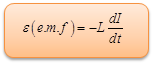
The figure given below describes inductance which explains the behavior of a wire in opposing any change of electric current through the coil. Derived from Faraday’s Law, inductance L may be defined in terms of the emf generated to oppose a change in current.
 Unit for L = volt per second/ ampere = Henry
The unit of measurement of inductance is Henries (H), which shows the dependence of rate of change of magnetic field. One henry is the amount of inductance that is required to generate one volt of induced voltage when the current is changing at the rate of one ampere per second. We have used here the term current rather than the magnetic field, because current can produce magnetic field and is easier to be controlled than the magnetic flux.
Consider the circuit, in which a solenoid is connected across a cell through a resistor. When the switch is open, the current in the circuit is zero. When the switch is closed, current flows in it. Since current in the circuit increases from zero to a certain value, magnetic field associated with it changes that causes induction of an emf across the solenoid.
Since ΦB = LI, and
∈ = -dφB/ dt
Hence, ∈ = - L dI/dt
Inductance of an Ideal Solenoid
Let a current I flow through a solenoid. The magnetic field due to the current flowing within the solenoid is, B = μ0nI, where n is the number of turns per unit length.
If area of cross section of the solenoid is A then flux associated with length l is equal to
Φ = nlBA. (Assuming that the solenoid is ideal and long)
where l is the length of the solenoid
Now B= μ0nI
So, ΦB= nBA
= (n) ( μ0nI) A
ΦB = μ0n2IA
Self-Inductance of a Coil
Consider a coil of N turns and area of cross section A, carrying a current I. The length of the coil is l (l ≥√A)
Comparing with Φ = LI, we get, L = μ0n2A
Simulation for Aluminum Ramp ( To view, please click on play button and go on)
Aluminum ramp; This animation shows how a magnet sliding on a ramp is affected by Lenz's Law. We use it to help illustrate a lab station the students do.
Problem (JEE Advanced):
A coil of inductance 1 H and negligible resistance is connected to a source of supply, whose voltage is given by V = 4 V. If the voltage is applied when t = 0, then find the cenergy stored in the coil in 4 s.
Solution:
We know that, V = L dI/dt
Or,

Thus energy stored, U = ½ LI2 = ½ (1) (32)2 = 512 J
From the above observation we conclude that, the cenergy stored in the coil in 4 s would be 512 J.

Inductive Reactance
The reduction in the flow of current in a circuit as a result of induction is called inductive reactance. On examining a coil of wire carefully and using the Lenz’s law, it becomes clear that inductance reduces the flow of current in the circuit. As in the figure given below, the primary current is shown in red and the magnetic field generated by the current is depicted in blue. In order to determine the direction of magnetic field, point your thumb of the right hand in the direction of current. The magnetic field from one loop of the wire will cut across the other loops in the coil and this will induce current flow, which is highlighted in green. According to Lenz's law, the induced current must flow in the opposite direction of the primary current. The induced current working against the primary current results in a reduction of current flow in the circuit.The inductive reactance will increase with the increase in the number of winds in the coil.
Inductive Reactance also reduces the flow of current in a circuit. But it is possible to distinguish inductive reactance from resistance in a circuit by noting the timing between the sine waves of the voltage and current of the alternating current. In an AC circuit that contains only resistive components, the voltage and the current will be in-phase, meaning that the peaks and valleys of their sine waves will occur at the same time. But in the presence of inductive reactance, the phase of the current is shifted so that its peaks and valleys do not occur at the same time as those of the voltage.
Refer this video to know more about inductance:-
|
|


Question 1
The property of coil by which a counter e.m.f. is induced in it when the current through the coil changes is known as,
(a) self-inductance
(b) mutual inductance
(c) series aiding inductance
(d) capacitance
Question 2
Which of the following circuit element stores energy in the electro magnetic field ?
(a) inductance
(b) condenser
(c) variable resister
(d) resistance
Question 3
Higher the self-inductance of a coil,
(a) lesser its weber-turns
(b) lower the e.m.f induced
(c) greater the flux produced by it
(d) longer the delay in establishing steady current through it
Question 4
Both the number of turns and the core length of an inductive coil are doubled. Its self-inductance will be,
(a) unaffected
(b) doubled
(c) halved

| Q.1 | Q.2 | Q.3 | Q.4 |
|
a |
a |
d |
b |
Related Resources
-
You might like to refer Series L-C-R Circuit.
-
For getting an idea of the type of questions asked, refer the Previous Year Question Papers.
-
Click here to refer the most Useful Books of Physics.
- To get answer to any question related to inductance click here.
View courses by askIITians


Design classes One-on-One in your own way with Top IITians/Medical Professionals
Click Here Know More

Complete Self Study Package designed by Industry Leading Experts
Click Here Know More

Live 1-1 coding classes to unleash the Creator in your Child
Click Here Know More