The Parallel Plate Capacitor
Table of Content |
Parallel Plate Capacitor
Parallel Plate Capacitors are the type of capacitors which are formed by arrangement of electrodes and insulating material (dielectric)
The two conducting plates act as electrodes which are separated by a dielectric between them.
The two plates of parallel plate capacitor are of equal dimensions and is connected to power supply. The plate which is connected to positive terminal of battery acquires positive charge while the plate which is connected to negative terminal of battery acquires negative charge. Due to the attraction charges store between the plates.

Fig.1: Parallel Plate Capacitor
Why Parallel Plate Capacitor is used?
Sometimes the electric charge to be stored in a capacitor is of high amount which can’t stored in a single capacitor. So, parallel plate capacitor are used which used two plates as electrodes which help to store more electric charge.
Principle of Parallel Plate Capacitor
As we know that certain amount of charge can be given to a plate as if more charge is applied its potential will increase and charge might leak.
If we get another plate and place it next to this positively charged plate then negative charge will be pulled towards the side of this plate which is closer to the positively charged plate and positive charge on the further side.

Fig. 2: Two plates of parallel plate capacitor
As both the plates have charges the negative charge on plate 2 will reduce the potential difference on plate 1 while the positive charge on plate 2 will increase the potential difference on plate 1. But the negative charge on plate 2 will have more impact.so more charge can be given on plate 1 because of negative charges on plate 2 the potential difference will be less.

Fig. 3: Plates of parallel plate capacitor
This is the principle of parallel plate capacitor.
Charging of Parallel Plate Capacitor

Fig. 4: Circuit for charging capacitor
Let C be the two plates of capacitor, V be the potential difference and k be the switch in figure 4.
Now when the key is closed then the electrons from the first plate start moving towards the positive end of the battery that is, there is flow of electrons from negative end to positive end of the battery
The electrons which moved towards to the positive end of battery from there they will start moving towards to the second plate. In this way both the plates will acquire charges, one will acquire positive charge while other will acquire negative charge.
This process will continue until the capacitor acquires potential difference V in the exact same amount that of the battery. Now the process will stop. At this time when the process has been stopped the capacitor has stored electric charge on it with the potential difference which is same as battery.
So now the charge can be written as:
Q = CV
Dependence of Charge Stored in a Capacitor
The amount of electric charge stored in any of the plate of parallel plate capacitor is directly proportional to the potential difference between the two plates of Parallel Plate Capacitor. This relation can be seen as:
Q α V
OR
Q = (constant) V
Where,
C = Capacitance of capacitor
Q = Amount of charge stored in one capacitor
V = Potential difference between the two plates
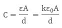
Capacitance of Parallel Plate Capacitor
The capacitance of parallel plate capacitor depends upon
-
The distance d between two plates
-
The area A of medium between the plates
-
According to the gauss law, the electric field can be written as:
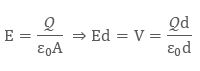
Since we know that the capacitance is defined as V = Q/C, so capacitance can be rewritten as:

When the plates areplaced very close and the area of plates are large we get the maximum capacitance.
Dielectric Material inserted between two plates

Fig .5: Dielectric placed between two electrodes
On the two plates, the microscopic dipole moment of the material will shield the charges. Thus will alter the effect of dielectric material which is inserted between the two plates Materials have a permeability which is given by the relative permeability k.
The capacitance is thus given by:
Capacitance of a parallel plate capacitor can be increased by introducing dielectric between the plates as the dielectric have permeability k, which is greater than 1. K is also sometimes known as Dielectric Constant.
Condition of parallel plate capacitor when medium is in air and in other substance
When in parallel plate capacitor the area between the who plates are partially filled with air and partially with other substance its Capacitance can be calculate.
Let there exist a parallel plate capacitor in which medium between the parallel plates is mainly the air and partially other substance as shown in figure below:

Fig. 6: Dielectric and air between plates
Multiplate Paralle Plate Capacitor
The arrangement of parallel plate capacitor with dielectric material between them in groups fitting in each other is known as Multiplate Parallel Plate Capacitor.

Fig. 7: Multiplate Capacitor
The capacitance of multiplate parallel plate capacitor can be calculated as:
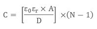
where,
A = Area of each plate
ε0 = Relative Permittivity of a Vacuum = 8.854 × 10⁻¹² F/m
εr = Relative Permittivity of Dielectric
D = Distance between plates
N = Number of Plates
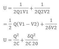
Charge on Parallel Plate Capacitor
Let us assume that a capacitor has capacitance C and have electric charge Q and the capacitor is electrically neutral
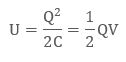
where V is the potential difference between the plates.
Now if the charge upon the two plates of parallel plate capacitor are different,then
V1 will be the potential difference of plate 1 with Q1 be the charge
While V2 will be the potential difference of plate 2 with charge Q2 = −Q + δQ
Electric Field on Parallel Plate Capacitor
The electric field is assumed from both the plates of parallel plate capacitor
E =σ/2ϵ0ñ
σ is the surface charge density on a single side of the plate,
Q/2A, since half the charge will be on each side.
More Readings
View courses by askIITians


Design classes One-on-One in your own way with Top IITians/Medical Professionals
Click Here Know More

Complete Self Study Package designed by Industry Leading Experts
Click Here Know More

Live 1-1 coding classes to unleash the Creator in your Child
Click Here Know More