

Grade 12th passMechanics
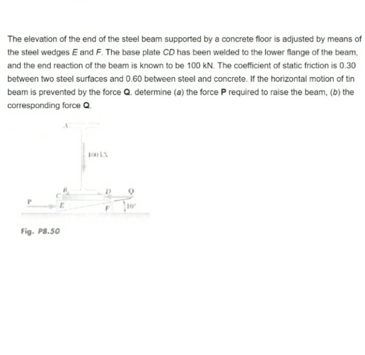
This question related to engineering mechanics. And on the elevation of end of steel beam supported
This question related to engineering mechanics. And on the elevation of end of steel beam supported


 Approved Tutor Answer1 Year ago
When discussing the elevation of the end of a steel beam supported in engineering mechanics, we delve into concepts related to structural analysis and the behavior of materials under load. The elevation of a beam's end can significantly impact its performance and the overall stability of the structure it supports. Let's break down the key aspects involved in understanding this topic.
In engineering mechanics, a beam is a structural element that primarily resists loads applied laterally to its axis. When we talk about the elevation of the end of a steel beam, we are often referring to how the beam is positioned and supported at its ends, which can be either simply supported, fixed, or cantilevered.
When a load is applied to a beam, it experiences deflection, which is the displacement of the beam from its original position. The amount of deflection depends on several factors:
To calculate the deflection of a beam, engineers often use formulas derived from beam theory. For a simply supported beam with a point load at its center, the maximum deflection can be calculated using the formula:
δ = (P * L^3) / (48 * E * I)
Where:
Understanding the elevation of the end of a steel beam is crucial for ensuring structural integrity and safety. Engineers must consider how deflection affects not only the beam itself but also the loads it supports, such as floors, roofs, or machinery. For instance, excessive deflection can lead to misalignment of structural elements, which may compromise the overall stability of a building.
Consider a steel beam used in a bridge. If the elevation at the ends of the beam is not properly accounted for, the bridge may experience uneven settling, leading to potential structural failure. Engineers must analyze the expected loads and design the beam accordingly to minimize deflection and ensure that the elevation remains within acceptable limits.
In summary, the elevation of the end of a steel beam supported in various configurations is a fundamental aspect of structural engineering. By understanding the types of supports, the factors affecting deflection, and the implications of these changes, engineers can design safer and more efficient structures.

Three identical balls are placed on a frictionless
horizontal surface touching each other. They stick to
each other because of adhesive. Another ball of same
radius and mass m is placed over the void created by
the three balls. Find the forces applied by the balls
kept on the floor to each other if the system remains
in equilibrium.
Last Activity: 10 Months ago
A car loaded with water having total mass 1000 kg moves on a straight horizontal Road starting from rest under the action of a force of 100 Newton. The water spills throw a small hole in the bottom at a rate of 0.1 KG per second the velocity of cart after 300 seconds is nearly.
11
21
31
41
Last Activity: 10 Months ago
Last Activity: 3 Years ago
Last Activity: 3 Years ago