

Grade 12th passMechanics
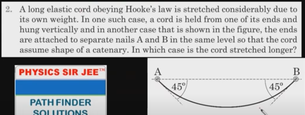
confused about the answe confused about free body diagram of dl lentgh element in first case
confused about the answe confused about free body diagram of dl lentgh element in first case


 Approved Tutor Answer1 Year ago
It sounds like you're grappling with the concept of free body diagrams, particularly in the context of a differential length element, often denoted as "dl." Let's break this down step by step to clarify what a free body diagram (FBD) is and how it applies to a differential element in mechanics.
A free body diagram is a visual representation used in physics and engineering to show all the forces acting on an object. It helps in analyzing the dynamics of the object by isolating it from its surroundings. In the case of a differential length element, the FBD will illustrate the forces acting on that infinitesimally small segment.
When we refer to a differential length element, we are typically dealing with a small segment of a larger object, such as a beam or a rod. This element is often represented as "dl" and is crucial for applying calculus in mechanics. The idea is to analyze the forces acting on this tiny segment to derive equations that describe the behavior of the entire object.
Imagine you have a uniform beam of length L that is simply supported at both ends and subjected to a downward force P at its center. If you want to analyze a small segment of this beam, say between x and x + dl, you would:
Once you have your FBD, you can apply the equilibrium conditions (sum of forces and sum of moments) to derive equations that describe the behavior of the entire beam. For instance, if the segment is in static equilibrium, the sum of the vertical forces must equal zero:
ΣF_y = 0
This will help you set up the necessary differential equations to solve for unknowns like deflection or internal shear forces.
By following these steps, you can create a clear and effective free body diagram for any differential length element, allowing you to analyze the mechanics of the system accurately. If you have a specific scenario or additional details, feel free to share, and we can delve deeper into that context!

Three identical balls are placed on a frictionless
horizontal surface touching each other. They stick to
each other because of adhesive. Another ball of same
radius and mass m is placed over the void created by
the three balls. Find the forces applied by the balls
kept on the floor to each other if the system remains
in equilibrium.
Last Activity: 9 Months ago
A car loaded with water having total mass 1000 kg moves on a straight horizontal Road starting from rest under the action of a force of 100 Newton. The water spills throw a small hole in the bottom at a rate of 0.1 KG per second the velocity of cart after 300 seconds is nearly.
11
21
31
41
Last Activity: 10 Months ago
Last Activity: 3 Years ago
Last Activity: 3 Years ago