PLEASE TELL ME ABOUT THE RC CIRCUIT AND EXPLAIN IT.......................
PLEASE TELL ME ABOUT THE RC CIRCUIT AND EXPLAIN IT.......................

Theresh Babu Benguluri , 13 Years ago
Grade 12
 Magnetism> RC CIRCUIT...
PLEASE TELL ME ABOUT THE RC CIRCUIT AND EXPLAIN IT.......................
 4 Answers
RC CIRCUIT MEANS CONSIST RESISTOR AND CAPACITOR
Dear Theresh,
Circuits with resistors and batteries have time-independent solutions: the current doesn''t change as time goes by. Adding one or more capacitors changes this. The solution is then time-dependent: the current is a function of time.
Consider a series RC circuit with a battery, resistor, and capacitor in series. The capacitor is initially uncharged, but starts to charge when the switch is closed. Initially the potential difference across the resistor is the battery emf, but that steadily drops (as does the current) as the potential difference across the capacitor increases.
Applying Kirchoff''s loop rule:
e - IR - Q/C = 0
As Q increases I decreases, but Q changes because there is a current I. As the current decreases Q changes more slowly.
I = dQ/dt, so the equation can be written:
e - R (dQ/dt) - Q/C = 0
This is a differential equation that can be solved for Q as a function of time. The solution (derived in the text) is:
Q(t) = Qo [ 1 - e-t/t ]
where Qo = C e and the time constant t = RC.
Differentiating this expression to get the current as a function of time gives:
I(t) = (Qo/RC) e-t/t = Io e-t/t
where Io = e/R is the maximum current possible in the circuit.
The time constant t = RC determines how quickly the capacitor charges. If RC is small the capacitor charges quickly; if RC is large the capacitor charges more slowly.
| time | current |
|---|---|
| 0 | Io |
| 1*t | Io/e = 0.368 Io |
| 2*t | Io/e2 = 0.135 Io |
| 3*t | Io/e3 = 0.050 Io |
What happens if the capacitor is now fully charged and is then discharged through the resistor? Now the potential difference across the resistor is the capacitor voltage, but that decreases (as does the current) as time goes by.
Applying Kirchoff''s loop rule:
-IR - Q/C = 0
I = dQ/dt, so the equation can be written:
R (dQ/dt) = -Q/C
This is a differential equation that can be solved for Q as a function of time. The solution is:
Q(t) = Qo e-t/t
where Qo is the initial charge on the capacitor and the time constant t = RC.
Differentiating this expression to get the current as a function of time gives:
I(t) = -(Qo/RC) e-t/t = -Io e-t/t
where Io = Qo/RC
Cracking IIT just got more exciting,It s not just all about getting assistance from IITians, alongside Target Achievement and Rewards play an important role. ASKIITIANS has it all for you, wherein you get assistance only from IITians for your preparation and win by answering queries in the discussion forums. Reward points 5 + 15 for all those who upload their pic and download the ASKIITIANS Toolbar, just a simple to download the toolbar….
So start the brain storming…. become a leader with Elite Expert League ASKIITIANS
Thanks
Aman Bansal
Askiitian Expert
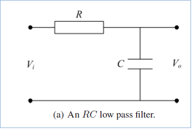
RC circuit u can use as low pass filter , it means it alows low freqency signal and attenute high frequency signal . This is beacause of at low frequency take w = 0 reactance of capacitor is ∞ then in circuit it is open circuit total voltage drope across open circuit , if it is high frequecny w = ∞ , reactance is 0 so it is act as short circuit so no voltage drop. reactance of capacitor is ( 1/( 2XπXfrequencyXcapacitance)) .
If you want about transient response RC circuit you can again ask me
thank u
RC circuit mainly used as low pass filter. That means it allows only low frequency signals and attenuates for large frequencies.
This can be explained from the impedance of the capacitor: Xc = 1/(jwc)
If the w increases the Xc decreases so influence of capacitor decreases.
It has particular frequency at which its response attenuates, this frequency known as cut off frequency.
This you can observe experimentally by CRO.

Prepraring for the competition made easy just by live online class.

Full Live Access

Study Material

Live Doubts Solving

Daily Class Assignments

Last Activity: 3 Years ago
Last Activity: 3 Years ago
Last Activity: 3 Years ago
Last Activity: 4 Years ago