Free Body Diagram
Table of Content |
It is to be noticed here that during previous examples, we were using a concept called FBD implicitly which can now be brought to you conscious attention.
It is like this. Whenever one attempts a problem involving forces and acceleration (say of dynamics or statics) one must show all forces and acceleration (possible acceleration may be unknown also) on each part of the system treating that part separately (it is called dividing system into possible subsystems). By all forces we mean external as well as internal forces (internal forces refer to mutual reactions). Now each system is ready to get treatment of laws of motion e.g. acceleration, velocity.
Coming to actual situation one should first identify all the component involved in the system, say mass m1, mass m2 .........., pulley 1, pulley 2, etc. Now separate them from others by cutting the string contacts (sort of imaginary separation) In effect, make them free (that's where comes the name free body) from other components and at the same time show all the forces acting on it, external as well as internal, arising due to separation from other parts. These are called mutual interaction forces (one of this type we have seen in the illustration of IIIrd law) and show all possible acceleration. The diagram thus obtained is called a free body diagram.
Refer This Video
Illustration:
Let us draw FBD for various given systems
[Here we are assuming that all the surfaces strings and pulleys are ideal that is we are neglecting their masses & any friction present]
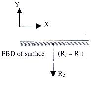
FBD (1) : Block of mass M is resting on a frictionless rigid surface
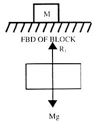
There are only two forces in the system in figure above. mg which is the weight of the block, and is acting on the surface. R2 = mg through its centre (since the body is symmetric). So, here itself from FBD we can see that net external force on the block is zero. That is why, it is stationary on the surface.
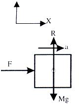
FBD (2) : Draw the free body diagram of the block shown in figure 1.12.
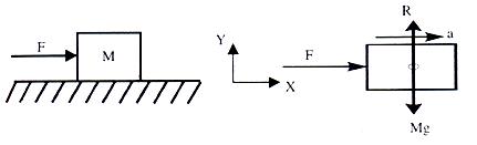
Where R is reaction from the surface (R = Mg)
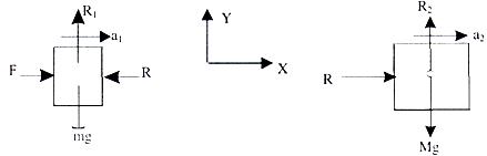
FBD (3) : Draw free body diagrams of both the blocks (figure 1.13 a), Assuming a reaction of magnitude 'R' is present at the interface.
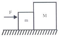
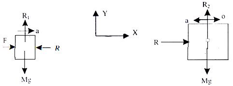
Now a question comes Can 'R' have a direction opposite to what is shown here? Answer is, of course it can have,
[before we proceed further let me point out that once you make calculations you will find that values of R will automatically come negative, which tells us that earlier direction were the correct ones].
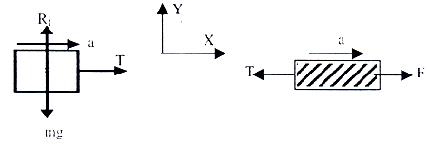
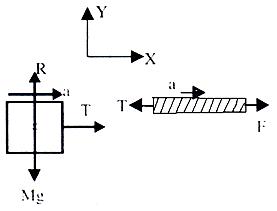
FBD (4) : Suppose situations is as shown in figure above that a light inextensible string pulls a block of mass M on a frictionless rigid surface.
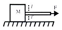
Here string is acting as a force transmitting element
It will experience a tension T in it. Let us cut it (imagine) at then the situation is as shown in figure shown below.
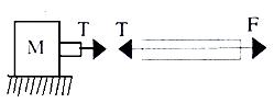
(We join it again then net force should become zero at that point. Since t, and T are oppositely directed their sum will come out to be zero).
So tension t is responsible for dragging mass of block.
Therefore free body representation is
Caution : What happens if rope is not massless?
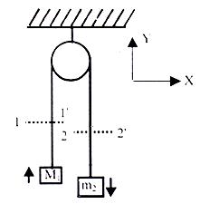
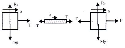
FBD (5) : Draw free body in case of system shown (figure shown below).
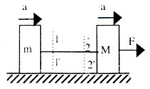
Suppose T is tension in the string, then by cutting it at 1-1' and 2-2' we can draw FBD's as shown in figure shown below.
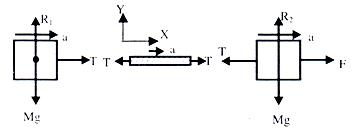
R1 and R2 are reactions from plane, and from Newton's law they are equal to the weights of respective blocks.
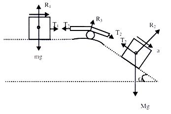
FBD (6) : Draw FBD where one of the block is resting on an inclined plane and rope goes over a frictionless massless pulley (Figure given below).
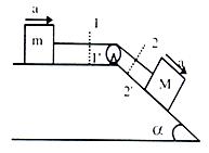
FBD becomes
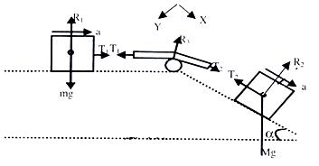
Here the noticeable fact is that R2 is perpendicular to the inclined plane and mg is perpendicular to horizontal plane. Since Mg is always directed downwards. R2 is due to the component of Mg, which is acting, perpendicular to inclined plane. (Here, the rule is that reaction force is always normal to the surface, which provides the reaction).
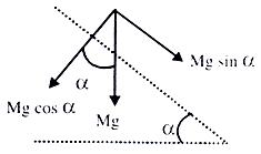
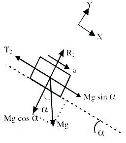
Here for "ease" we can resolve force Mg in two components. One parallel to inclined plane and other on perpendicular to inclined plane. As shown in figure below.
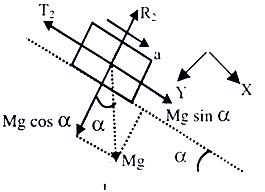
.·. free Body, of the block on the inclined plane can be represented by figure shown below.
Finally at the end of this FBD, I want to point out that T2 will always be equal to T2for a continuous homogeneous massless inextensible string passing over a massless frictionless pulley.
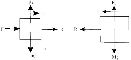
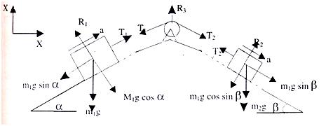
FBD (7) : Suppose both the block are on inclined planes as shown in figure given below.
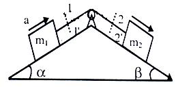
For FBD cut the strings at 1-1' and 2-2' and separate the two blocks and pulleys as subsystems.
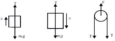
FBD (8) : If pulley is hanging from a rigid support say roof and masses are connected as shown in figure given below.
FBD's become.
Once we are comfortable in drawing FBD then we can proceed to write equation of motion, using Newton's II Law. But prior to that, it is necessary to briefly introduce you with the concept of equilibrium of bodies.
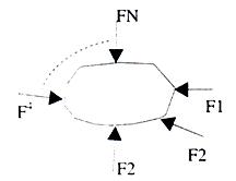
Equilibrium:
An object is said to be in equilibrium if the vector sum of all the forces acting on the body (externally applied + forces arising due to mutual interaction;) is zero.
That is  1 + 2 +......+ N = 0
But since it is impractical to apply it, as it is, to problems, therefore we resolve all forces in the three directions X, Y & Z equilibrium and if some of the forces is zero in each direction then the body is said to be in equilibrium. (to be more specific - translator equilibrium).
F1x + F2x + ............ + Fnx = 0
F1y + F2y + ............ + Fny = 0
F1z + F2z + ............ + Fnz = 0
Enquiry : How to Apply Equations of Motion to Any Problem?
Writing Down Equations of Motion: Once we have made a free body diagram then we can write equations of motion for each part of the system, for which we have drawn FBD. To write down equations of motion for a sub-system for which we have already drawn the FBD the requirement is to choose two direction (if required we will need three directions) in which we shall work to reduce the complexity say, direction X and Y which in most of the cases is natural. In other cases, where we are dealing with inclined planes we can fix our coordinate axis x-y in any desired orientation which reduces our trouble of finding out components of the forces which are acting in various directions and by experience one knows that it is better to choose X axis parallel to the inclined plane and Y axis perpendicular to it. For inclined plane
  is the right choice of coordinate axis, tilted as per inclination. Now once can go for writing F = ma equations in two directions for any ith sub-system.
∑Fx = miax
∑Fy = miay
Let us write down equation of motion for the FBD's we have already drawn.
Refer to FBD (2): Here figure is given below.
∑Fy = R - Mg
It will be zero since we know that on the surface the body can't move upwards or downwards.
.·. R - mg = 0 => R = Mg and ∑Fx = F
And this alone should accelerate it
∑ F = Ma, => a = F/m
Refer to FBD (3): Here Figure is given below.
for the smaller block
∑Fy = R1 - mg = 0 .·. R1 = mg
∑Fx = F-R .·. F-R = m a1
For the Large Block ∑Fy = R2 - Mg = 0 .·. R2 = Mg
∑Fx = R .·. R = Ma2
Since both Blocks move as on system, their accelerations will be equal
a1 = a2 .·. F - R = ma
& R = Ma from here we can solve for R & a.
Refer to FBD (4): Here figure is given below.
For block
∑Fy = R - Mg = 0
.·. R = mg
∑Fx = T = Ma
.·. a = T/m
Refer to FBD (5): Here Figure is given below.
Here also, since system is fully connected and we assume that string is not loose, then the acceleration in different parts will be equal. That is, Blocks m and M as well as the string will move with the same acceleration 'a'.
Equation for smaller Block
∑Fy = R1 - mg = 0
.·. R1 = mg
∑Fx = T = ma ............ (1)
For Block - 'M' ∑Fy = R2 - Mg = 0
.·. R2 = Mg
∑Fx = F - T = Ma ......... (ii)
solving (i) & (ii) we get T & a.
Refer to FBD (6): Here Figure is given below.
Since, system is fully connected by light inextensible string therefore acceleration in all the parts will be equal.
For Block 'm'
R1 - mg = 0 .·. R1 = mg
T1 = ma.
For Block 'M' (Refer to the diagram made with mg cos α & mg sin α components.
R2 - Mg cos α = 0 (since it is not moving to the plane)
R2 = Mg cos α and is parallel to the plane
Mg sin α - T2 = Ma ............ (ii)
It is already explained that T1 = T2 = T
.·. solving (i) & (ii) we get 'T' & 'a' for the system.
Refer to FBD (7) : Here Figure is given below.
T1 = T2 = T (similar to the analysis done in FBD (6))
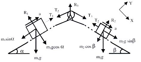
For block m1 perpendicular to inclined plane T1 - m1g cos α = 0 R1 = m1g cos α.
Parallel to the plane.
T-m1g sin α = m1a ............. (1)
For block m2 perpendicular to plane
R2 - m2g cos β = 0 R2 = m2g cos β and m2 g sin β - T = m2 a ...... (ii)
Solving (i) & (ii) we get 'a' & 'T.
Refer to FBD (8) : Here Figure is given below.
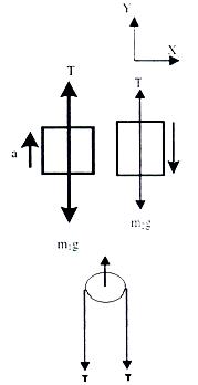
In Y-direction :
For block m1 T - m1g = m1a
For Block m2 m2g - T = m2 a
From (i) & (ii) we can solve for 'T' & 'a'.
On pulley 2T force is acting downwards. Therefore the pulley experiences a force F = 2T. Now you are well conversant with making FBD's and writing down equations of motion for the given system. Therefore, now we can write down some definite steps to follow for any given problem, which can considerably reduce your diversion or confusion or say the possibility of getting trapped into complexity of a problem. (of course for that you have to use your brain all the time with these steps).
(i) Draw the fully connected clear diagram.
(ii) Define subsystems, that is parts of the system on which you will work to get your answers.
(iii) Draw free body diagrams for all possible subsystems.
(iv) Resolve forces as well as accelerations in x y & z direction. (or perpendicular and || to the plane whenever require).
(v) Write, ∑Fx, ∑Fy, ∑Fz equations with the physical constraints appearing in the problem.
(vi) Eliminate some variables and get the required one(s).
Centripetal Force
If a body is moving with a constant speed in a circle, as seen from an inertial frame, it is continuously towards the centre of rotation with magnitude vr/r (known as centripetal acceleration), where v is the speed of the particle and r is the radius of the circular path.
According to Newton's second law, this body will experience net force directed towards the centre called the centripetal force.
Therefore, net force acting on the body towards the centre = mv2/r, where m is mass of body.
Centrifugal force is a pseudo force acting on the body from a rotating frame.
Illustration:
A bob of mass m is suspended form a inextensible, massless describe a horizontal uniform circular motion as shown in figure 1.42. about a vertical. Analyze the dynamics of this system.
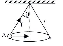
Solution:
The path of the system described above is shown in figure 1.42. Let the radius of circular path of bob is r equal to l sin θ and tension in string is T. The string makes an angle θ with the vertical. Consider the bob is at A. We can draw the free body diagram of bob at a as shown in figure 1.43. The force acting on the bob is it's weight mg and tension T of the string. Tenstion T is resolved in two components T cos θ and T sin θ as shown in figure 1.43. we can write the equation of motion
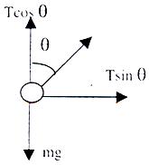
T cos θ = mg T sin θ = mv2/r
To read more, Buy study material of Laws of Motion comprising study notes, revision notes, video lectures, previous year solved questions etc. Also browse for more study materials on Physics here.
View courses by askIITians


Design classes One-on-One in your own way with Top IITians/Medical Professionals
Click Here Know More

Complete Self Study Package designed by Industry Leading Experts
Click Here Know More

Live 1-1 coding classes to unleash the Creator in your Child
Click Here Know More